RESOURCES
INDUSTRY LEADING METAL FORMING RESOURCES
On this page we hope to provide common terminology, bending forms and additional information that you may find useful in helping describe your product to us. If you have any additional questions please feel free to contact us.
Common Bending Terms
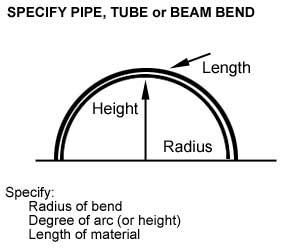
- Arc – The degree of bend for the curved portion of an pipe, tube or beam.
- Bevel – A type of end finishing for a pipe, tube or beam.
- Centerline Radius (CR) – Distance from the center of curve to the centerline axis of the pipe, tube or beam. Abbreviated as CLR.
- Cold Bending – Using cold shaping methods to bend a pipe or other object.
- Degree – An increment of angle to form a bend above the plane of 0 degrees, to which the bend is formed (i.e. 10, degrees, 45 degrees, 90 degrees, 180 degrees, etc.) See Diagram
- Easy Way (EZ) – Bending of a rectangular pipe, tube or beam along its shortest dimension of length.
- Hard Way (HW) – Bending of a rectangular pipe, tube or beam along its thickest dimension of length.
- I.D. – The Inside diameter of the pipe or tube.
- Neutral Axis – The unbent portion of an object (pipe, tube or beam) that is neither compressed or under tension due to bend.
- O.D. – The Outside diameter of a pipe, tube or beam in inches.
- Out of Plane – The deviation from a horizontal plane of rectangular object by a single bend, between its tangent points and the centerline of the bend.
- Ovality – The distortion of pipe or tube from it’s a circular shape caused by bending.
- Material Grade – Manufacturers’ specification of material for pipe, tube or beam material, (i.e. A53B, T304W SS).
- Plain End – Square cuts made to a pipe, tube or beam prior to bending.
- Roll Past – Degree or fraction of degree that a pipe, tube or beam is bent beyond a specified point.
- Rough Cut – Pipe, tube or beam end cuts that are not required to be straight.
- Square Cut – End cuts to a pipe, tube or beam that are square to the centerline of a bend after the bending process.
- Tangent – The straight portion of material on either side of arc of a bend.
- Tangent Point – A point where the bend of a pipe, tube or beam begins or ends.
- Taper Bore – A milling or grinding out of the inside diameter of the end of a bend to create a tapered pipe or tube diameter.
- Wall – The thickness in inches of the outside wall of a pipe or tube.
- Wrinkles – Ribbed or wavy indentations in the inner bend angle of a bend of a pipe, tube or beam.
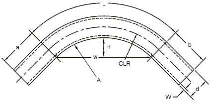
| a – First straight
b – Second straight d – pipe or tube diameter L – Length of BendH – Height of Bend |
A – Degree of Bend
W – Material wall thickness w – Width of bend CR – Centerline Radius |
|
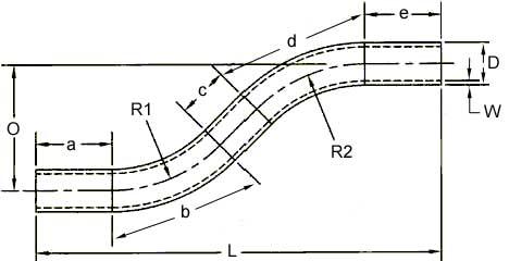
a – First straight b – First bend c – Mid-straight d – Second bend e – Last straight |
O – Height of offset L – Length of offset R1 – First radius R2 – Second radius W – Tube wall thickness D – Tube outside diameter |
Design Procedure for Bent Tubular Products
1. Research material available and bendability to determine design feasibility. Use bend radii of (2-D) 2 x O.D. of tube or greater when design permits. Always use existing tooling if possible to avoid expensive die costs.
2. When possible, always avoid bends too close together or bends within bends. This type of design requires special tooling and will greatly increase piece part costs.
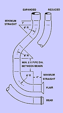
3. Make all bend radii on tube being designed same radii to minimize production costs. Allow minimum of 2 X tube diameter between bends for clamping. Check with BOYCE for clamp length information.
4. Avoid expanded and reduced ends too close to bend tangent. Allow 1″ minimum on expanded or reduced ends and 4″ for flare, bead or end finishing.
5. Bend radii smaller than (2-D) 2 X tube diameter will result in specialized tooling and material. Always use the largest radius possible when designing bent parts to avoid premium bends. All rounds are designed on a centerline radius, squares and rectangles on an inside radius.
6. Bend tolerances on single bend parts are +/- 1º. On multiple bend parts +/- 1-1/2º and +/- 3/32 c-c up to 2-1/2″ and +/- 2º of bend +/- 3/16″ above 2-1/2″. Tube cutting tolerance +/- 3/32″ unless otherwise specified on part print, our quotations are based on these tolerances. Try to avoid machine tolerances and true radius dimensions on bend drawing specifications.
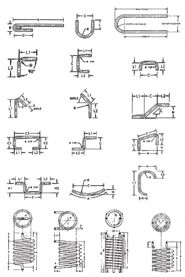
Common Bending Shapes
Specifications
| Maximum Allowable Working Pressures for common boiler tube sizes, SA178A or SA192, where expanded into drums or headers. From ASME Boiler & Pressure Vessel Code, Section I, Table PWT-10. This information is copyrighted by ASME, and is reproduced with permission. This table is presented for information only, and is not a substitute for proper ASME design procedures. | ||||||||||||||||||||||||||||||||||||||||||||||||||||||||||||||||||||||||||||||||||||||||||||||||||||||||||||||||||||||||||||||||||||||||||||||||||||||||||||||||||||||||||||||||
| Tube Outside Diameter, inches | ||||||||||||||||||||||||||||||||||||||||||||||||||||||||||||||||||||||||||||||||||||||||||||||||||||||||||||||||||||||||||||||||||||||||||||||||||||||||||||||||||||||||||||||||
|
| Common Boiler Tube Specifications | ||||||||||||||||||||||||||||||||||||||||||||||||||||||||||||||||||||||||||||||||||||||||||||||||||||||||||||||||||||||||
|
|
||||||||||||||||||||||||||||||||||||||||||||||||||||||||||||||||||||||||||||||||||||||||||||||||||||||||||||||||||||||||
| For boiler tubes, A-178A is the most common, and most economical choice. | ||||||||||||||||||||||||||||||||||||||||||||||||||||||||||||||||||||||||||||||||||||||||||||||||||||||||||||||||||||||||
| Economizers are usually made from SA-178A or SA-210-A1. | ||||||||||||||||||||||||||||||||||||||||||||||||||||||||||||||||||||||||||||||||||||||||||||||||||||||||||||||||||||||||
| Superheater materials vary widely, with SA-178A and SA-192 used most often in the lower temperature ranges. SA-210-A1, SA-213-T11, and SA-213-T22 are commonly seen in the intermediate temperature ranges, with the stainless grades, most frequently Tp-304H and Tp-347H, reserved for the higher temperature superheaters, although SA-213-T91 is increasingly specified for the highest temperatures. |
| Standard Pipe Dimensions and Weights | |||||||||||||||||||||||||||||||||||||||||||||||||||||||||||||||||||||||||||||||||||||||||||||||||||||||||||||||||||||||||||||||||||||||||||||||||||||||||||||||||||||||||||||||||||||||||||||||||||||||||||||||||||||||||||||||||||||||||||||||||||||||||||||||||||||||||||||||||||||||||||||||||||||||||||||||||||||||||||||||||||||||||||||||||||||||||||||||||||||||||||||||||||||||||||||||||||||||||||||||||||||||||||||||||||||||||||||||||||||||||||||||||||||||||||||||||||||||||||||||||||||||||||||||||||||||||||||||||||||||||||||||||||||||||||||||||||||||||||||||||||||||||||||||||||||||||||||||||||||||||||||||||||||||||||||||||||||||||||||||||||||||||||||||||||||||||||||||||||||||||||||||||||||||||||||||||||||||||||||||||||||||||||||||||||||||||||||||||||||||||||||||||||||||||||||||||||||||||||||||||||||||||||||||||||||||||||||||||||||||||||||||||||||||||||||||||||||||||||||||||||||||||||||||||||||||||||||||||||||||||||||||||||||||||||||||||||||||||||||||||||||||||||||||||||||||||||||||||||||||
| Use this table to find dimensions and weights for standard steel, alloy, and stainless steel pipe. Many additional diameters and schedules are available – only the more common ones are shown here. | |||||||||||||||||||||||||||||||||||||||||||||||||||||||||||||||||||||||||||||||||||||||||||||||||||||||||||||||||||||||||||||||||||||||||||||||||||||||||||||||||||||||||||||||||||||||||||||||||||||||||||||||||||||||||||||||||||||||||||||||||||||||||||||||||||||||||||||||||||||||||||||||||||||||||||||||||||||||||||||||||||||||||||||||||||||||||||||||||||||||||||||||||||||||||||||||||||||||||||||||||||||||||||||||||||||||||||||||||||||||||||||||||||||||||||||||||||||||||||||||||||||||||||||||||||||||||||||||||||||||||||||||||||||||||||||||||||||||||||||||||||||||||||||||||||||||||||||||||||||||||||||||||||||||||||||||||||||||||||||||||||||||||||||||||||||||||||||||||||||||||||||||||||||||||||||||||||||||||||||||||||||||||||||||||||||||||||||||||||||||||||||||||||||||||||||||||||||||||||||||||||||||||||||||||||||||||||||||||||||||||||||||||||||||||||||||||||||||||||||||||||||||||||||||||||||||||||||||||||||||||||||||||||||||||||||||||||||||||||||||||||||||||||||||||||||||||||||||||||||||
|
|||||||||||||||||||||||||||||||||||||||||||||||||||||||||||||||||||||||||||||||||||||||||||||||||||||||||||||||||||||||||||||||||||||||||||||||||||||||||||||||||||||||||||||||||||||||||||||||||||||||||||||||||||||||||||||||||||||||||||||||||||||||||||||||||||||||||||||||||||||||||||||||||||||||||||||||||||||||||||||||||||||||||||||||||||||||||||||||||||||||||||||||||||||||||||||||||||||||||||||||||||||||||||||||||||||||||||||||||||||||||||||||||||||||||||||||||||||||||||||||||||||||||||||||||||||||||||||||||||||||||||||||||||||||||||||||||||||||||||||||||||||||||||||||||||||||||||||||||||||||||||||||||||||||||||||||||||||||||||||||||||||||||||||||||||||||||||||||||||||||||||||||||||||||||||||||||||||||||||||||||||||||||||||||||||||||||||||||||||||||||||||||||||||||||||||||||||||||||||||||||||||||||||||||||||||||||||||||||||||||||||||||||||||||||||||||||||||||||||||||||||||||||||||||||||||||||||||||||||||||||||||||||||||||||||||||||||||||||||||||||||||||||||||||||||||||||||||||||||||||

A NAME YOU CAN TRUST
With over 32 years of industry leading experience, Metal Forming Solutions has become a reliable source for innovative solutions and high quality products. With outstanding Customer Service that goes above and beyond our customers’ expectations service and uncompromising Integrity, we believe that you simply won’t find a better choice.
Metal Forming Solutions is the leading provider of forming solutions and bending services for a various industries with a multitude of applications used worldwide.
Let’s talk about getting your next project done.



Contact Information
Metal Forming Solutions
7512 Charles Page Blvd, Tulsa, OK 74127
Phone: (918) 241-0514
Fax: (918) 241-0516
Toll Free: (866) 637-5805
Email:
Business Hours (CST)
| Monday | 8AM–5PM |
| Tuesday | 8AM–5PM |
| Wednesday | 8AM–5PM |
| Thursday | 8AM–5PM |
| Friday | 8AM–5PM |
| Saturday | Closed |
| Sunday | Closed |
